Vertex Welding Issues
This tutorial will cover the basics in verticy welding. This is a huge issue in games, since any two edges that share the same location in space with their verts not welded will flicker. I will go through some methods on either fixing these issues, or hiding them with the rest with the surrounding geometry.
Checking:
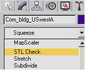
The first step is to identify the obvious issues with the mode. It is hard to separate what is modeled correctly, but Max has a tool to help you. This tool is called “STL check” and can be found under your Modifier list drop down.
With your mesh and “STL Check” modifier selected, do the following.
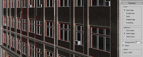
Click “Open Edges”
Click “Select Edges”
Un-check “Change Mat_ID”
Click “Check” to see where the open edges are on your asset. It should look something like this.
Every red line you see in the image above is an open edge. The verts of these edges are not welded, and unless they intersect with a face, the verts are welded, or there is geometry behind it, the geometry most likely will flicker at these sections when viewed at the correct angle.
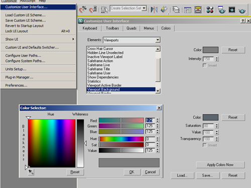
I changed my 3D Max viewports background to a bright green so it is easier to see these seams (as well as any obvious holes in the mesh).
You can change it by going to 'Customize/ Customize User Interface' click on the 'Colors' tab, and under 'Elements' scroll down to 'Viewport Background'. To the right, you will see a box with 'Color' to the left of it. Here is where you can change your background. It will not update until you close the 'Customize User Interface' window.
To change it back, simply open the same customize window, and click 'Reset' on the far bottom right, or click on the color, and chance the RGB colors all to 125.

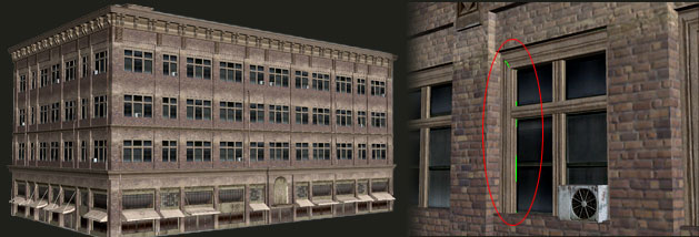
When the window ledge is pulled out (Left img.), you see that the vertices are not welded on the window. There are two methods you can take to fix this issue. You can either weld the verts, or intersect the edges into neighbouring faces to hide the seams.
1.) Make sure any edges sharing the same space are split and welded so there is no seam in the geometry.
2.) Intersect the edges into existing polygon faces. (hiding the seam)
The up side to option 1 is that you guarantee no flickering along that edge; the down side is that you need to either weld the verts where they meet the wall (which will increase poly count). In this case, extruding the edges into the geometry (option 2) will save some geometry down the road. The images below will better describe this.
Understanding and fixing:
These image show issues with the window, what to look for, and how it should look in the end.

1.) the horizontal section needs to intersect the surrouding walls to stop any flickering.
2.) Instead of having the windows in 4 pieces, they should be one solid piece, and either be welded or intersect the surrounding walls.
3.) the section that connects with the window frame in this area will flicker. a before and after image shown below will better illustrate how to fix this.

The middle horrizontal edge was moved in so it is not flush with the wall (also gives more geo for shadows to play with) the window is now one sloid piece, and welded to the corners of the wall, and the veritcle wall is split to weld at the corners of the windows.
Tips and tricks:
If you need to split any geometry, or aulter a piece that is already textured, here are a few quick and easy steps to achieve it while maintaining your UV layout. (Refer to image below)
If you need to split any geometry, here are a few quick and easy steps to achieve it. (Refer to image below)

1.) In this example, the smaller wall piece that attaches to the larger wall will have flickering issues.
2.) If you select the edges and select 'Connect' under the 'Modify/edit Edges' menu, or use the cut tool, there is a good chance the edge will notbe even.
3.) If you flatten the edge manually, it will most likely twist the texture and distort it like you see here.
4.) If you move it, it will stretch and squash the texture.
5.) The best way to get around this issue is under the 'Modify/Edit Geometry' there is an option called 'Preserve UV's' this tool works best with 3 or 4 sided faces, so be careful of this small fact.
6.) Now when you move the edge up or down, it does not distort the texture.
7.) Another way of cutting the face which is quicker and more accurate is the following. Select the polygon face you want to cut.
8.) Under your 'Grid and Snap Settings' (right click on the snaps toggle, the magnet with a 2, 2.5 or 3 above it) and click on 'Vertex'.
9.) Under the modify menu/Edit Geometry, select 'Quick Slice'.
10.) On the face, click on one edge you want to create an edge on, and select the other. It will snap the edge created to the vert, and if the face has a vert that it can weld to, it will do so.
11.) On a side note. If you want to quickly flatten any edge, vert or face, this is a good trick to make sure it's completely flattened. When you select any edge, vert or face, you get your orientation tool which shows what direction it is facing.
Red - X
Green - Y
Blue - Z
If you want to flatten your face in say the X axis, make sure you have the middle or bottom button of your 'Select and non-uniform scale' button, located to the left of your 'view' drop down. Also on the bottom of your max, click on the 'Absolute mode transform Type-in'. Once that is selected, the read out for the X, Y and Z axis will all read 100. To flatten on the X axis, type in 0 in the place of the 100, and your edge, vert or face will be flattened along this axis.
12.) And finally, when you have finished cutting your geometry, don't forget to delete the un-wanted face, and weld the verts after. 3D Max does not allow for more than two faces to be assigned to a single edge, unlike some applications such as Maya, so the welding must be done after the face is deleted.
Recap:

1. As long as every vert is welded, this will work just fine.
2. As long as the geometry collides, this will work, however this can give strange shadows on any vertex lit geometry.
3. This will not work all of the time. There are no welded verts, and no edges intersect a face (or blocked by geometry behind the seam). At the wrong angle, this may cause flickering.
I hope this little tutorial has helpd you out. i thank you for your time.