UT3: Pylon texturing

UT3: How to set up a more in depth materialfor this pylon.
This tutorial will go more in depth with the things the UT3 material editor can do and how to achieve certain effects.
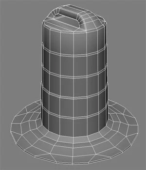
First, we need a model as shown above. This is a simple street pylon that has two states; clean and destroyed. The two models have the exact same geometry and uv's to make sure the normal map, spec and diffuse all match the other version. We will also be creating two other materials inside ut3 to add more grime and dirt.
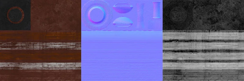
First let’s look at the textures we have created for this asset when imported into the UT3 engine.
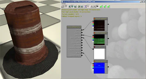
When the textures are placed in a material and assigned to a mesh inside max, this is the result you get. Not very nice now is it.
There are a number of issues with this asset. The spec is not ideal, there is no reflections on the reflective tape, and over all it just looks dull. Let’s fix all that shall we.
First, let’s go over why my spec has those green lines on it and looks different from what I showed up above. The spec for this asset only requires a black and white value. If you look at any texture inside Photoshop, each red green and blue channel is a black and white value. All 3 of these combined will give you a coloured picture. I simply placed the spec in the red channel, a mask which we will use later on in the green channel, and the blue is available for any other use needed. Since this will all be a part of a single texture in the end, we are saving texture information. These are the channels and the final
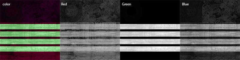
texture:
Red – spec
Green – mask
Blue – currently not being used on this asset
For the pylon asset, lets bump up the spec a little bit to give a bit more form to show off the normal map a bit more. I have to be careful not to increase the value too high or it will not look believable at all.
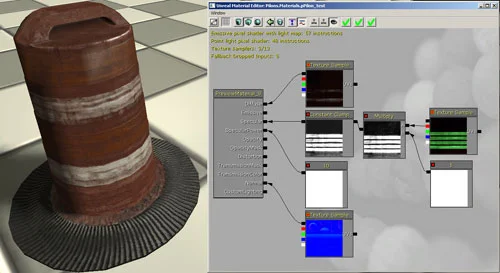
This tweak consists of the spec map going into a 'Multiply' channel A with A 'Constant' with the value of 5 going into channel B. All of that is then fed into a 'Constant Clamp' which clamps the value of which you choose. For this asset it is 0 and 1. You can go into the texture and tweak this, but the back and forth can be a little troublesome and time consuming after a while. The easiest way to see how things look in game is to tweak them inside the editor. This change pumps up the spec value over all but caps the white strips at a 100% white value.
These pylons have a reflective tape; putting it in is where the spec green spec channel comes into play. First I found an environment map that worked best for me with a good light and dark variation. Combined with the normal map, it gave me an idea of what it will look like.
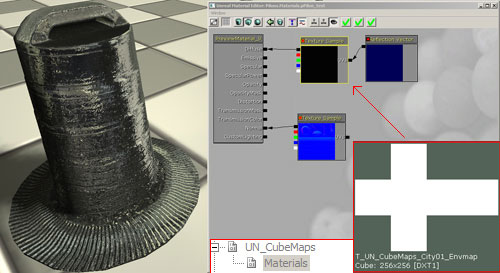
The next step is to add this to the diffuse while not ruining it.

The green spec channel is connected to the alpha of a lerp. The diffuse is connected to the A channel of the lerp, and the reflection texture to the B channel of the lerp.
Note: the white of any texture plugged into the alpha of a Lerp controls channel B, black controls channel A.
Great, but this reflective tape needs some kind of texture to bump it out a bit and give it a more reflective feel.

This is where this texture comes in. Sure it's small, but it doesn't have to be that big at all, just large enough to contain the detail we are looking for.
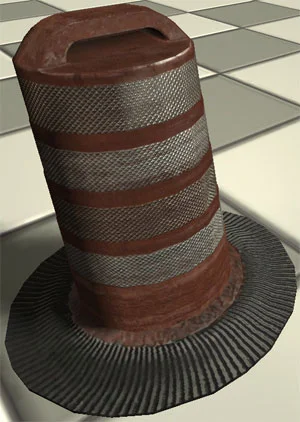
With the addition of this texture, this is the result you get. This would be the cleanest I would recommend making something if you're going for a realistic environment. If you go any cleaner than this you risk making something TOO clean which then makes it not believable. The real world always has variation in colors, grime and dirt, aged looks, scratches, dings, bumps, bleaching from the sun, stains from rust... the list goes on.
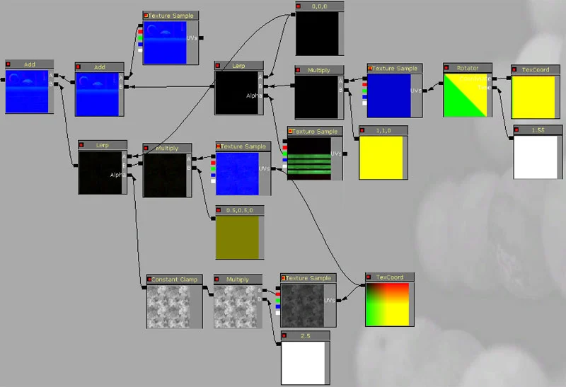
Below is an image of the hierarchy for how this normal map was added. Below that I will go more in depth as to how it was put together and what every variable does.

Bringing in the normal map texture is simple enough, but we need to rotate it. I created the normal map sideways because the texture is so small and the pixels line up vertically and horizontally, not on an angle. You achieve more detail creating a texture this way and then rotating it in UT3.
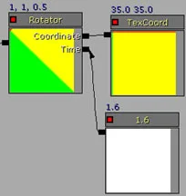
First let’s start with the rotation. The 'Rotator' node is what's needed to rotate your texture. The 'TexCoods' is plugged into the 'Coordinate' and is repeated 35 times both in the U and the V. The 'Constant' variable is what's used to set the time for repeating. This can be confusing, but it's not as bad as you may think. The 'time' variable inside the 'Rotator' node is how fast time passes, when you plug in a constant variable into the 'time' slot, it sets a consistent value based on how much the texture would be rotated based on the white value plugged in there. There are infinite possibilities for setting up these two values, but thankfully you can simply use the visual guide on the 'Rotator' to see what angle your texture is.
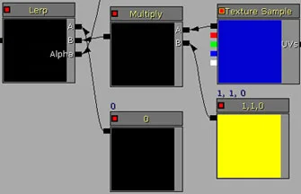
The 'Rotator' is the plugged into the texture sample. Just like in the 'basic material' tutorial, you plug the texture into a multiply with a 'Constant3Vector' with the setting of 1,1,0 to cancel out the blue channel we do not want. This is then inserted into the B channel of a lerp with a constant (0 Value) plugged into A and the alpha is the green channel of the spec. Again, sounds complicating, but it's not quite that bad. The green channel is used to decide where the normal map detail will be placed. Again, the white instructs where the texture plugged into channel B is. All of this is then plugged into an 'Add' variable with the original normal map. Since you are 'Adding', the black is simply dropped, and the only thing merged in with the original normal map is in the strips of the reflective tape.
Great. This asset can be left how it is currently, however I want variation. Instead of changing the base textures of the diffuse, spec and normal map, I am going to overlap a new normal map and diffuse to give more variation for 2 more materials.
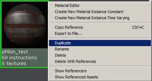
Right click on your current material and select 'Duplicate'. Re-name it to what you would like the new material to be named.
The new material can get a little messy, but the main changes are highlighted below.

Note: the orange arrows are there because I had them selected when I took the screen shot to easily show where the textures are plugged into.
Diffuse:
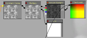
This is a new texture applied to the UT3 engine. The texture is a 512X512 and is repeated twice (effectively doubling the pixel detail of the original model). The texture is then 'Multiplied' 2.5 times and 'Clamped' at 0 and 1 to make sure there is no over exposure of the texture.

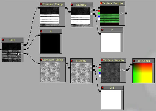
This hierarchy was re-arranged to better show the flow of the material. The green channel of the spec is inserted into a lerp with the A channel being set to 0 with a 'constant' variable and the B channel having the new detail texture plugged in. This is then plugged into the original 'Lerp'. This step is done to cover up the 'reflection' on the dirty areas
I placed in in-between lerp to add grime to the overall texture. The alpha channel is the detail texture, channel A is the original lerp, and channel B is set to 0 using a 'constant' variable.
Spec:
This hierarchy was also re-positioned to make it easier to visualise.
The same dirt layer is driving the alpha of a 'Lerp'. Channel A is the original spec texture and channel B is a simple black texture using a constant set to 0. That is then plugged into the spec channel.
Normal:
The same method we used to add the 'reflective' normal map texture will be applied here, however we do not need to use the spec as a mask, instead we will be using the dirt texture.
The dirt texture is repeated twice, so the normal map created from that dirt texture is also repeated twice. I only needed half the height so the 'Constant3Vector' is set to 0.5, 0.5, 0. This is then inserted into a 'Lerp'. The alpha channel is the dirt texture, channel A is black being driven by a constant variable set to 0, and channel B is the normal map texture. All of this then goes into an 'Add' node which ignores all the 0 values (black texture) causing only selected areas to receive normal map. The reason why we use a lerp to choose where we want the normal map to be is because when we multiplied the original grime texture, we tightened the variation between solid black and solid white, which was clamped by the 'Constant Clamp' to make sure the 100% white strength was not exceeded.
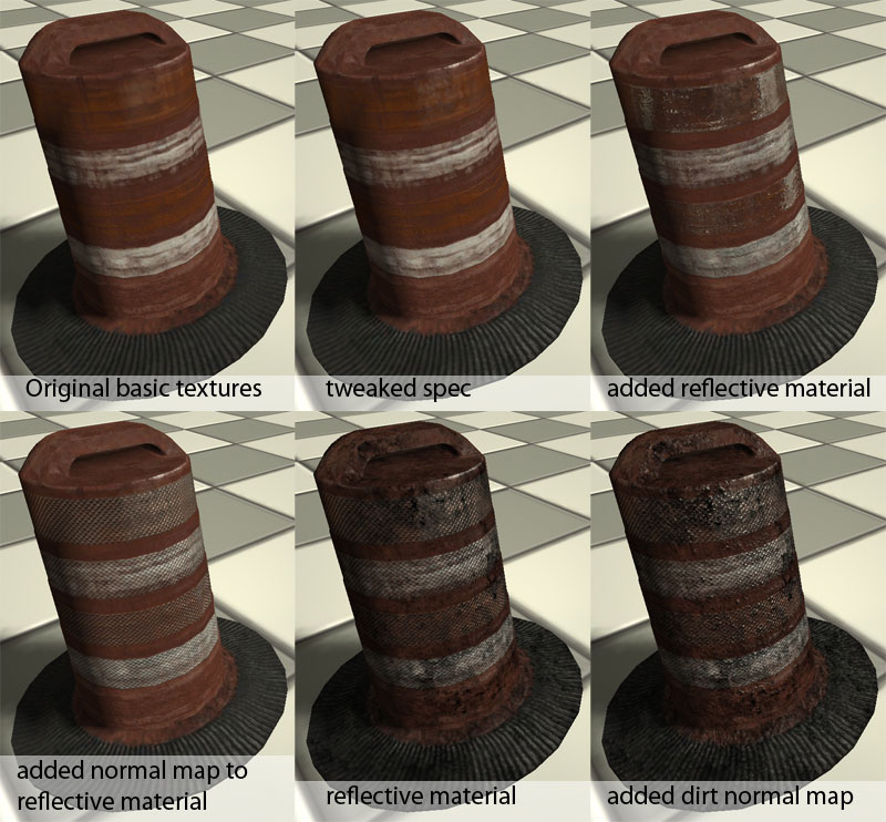
The images below shows the progress through this tutorial and the drastic changes from the before and after that can be achieved if done correctly.
I hope this little tutorial has helped you out. i thank you for your time.