UDK – Unreal Development Kit
World Position Offset

Click here for Youtube link.
This tutorial will cover the 'world position offset' node located at the bottom of the material editor. I have a 'YouTube' video with this tutorial to make it easier to grasp, so please check that out. If you need 'step by step' instructions on how to set everything up in detail, that's what this tutorial is for.
http://www.youtube.com/watch?v=cfTzUwDeUbM
This is an idea of what this function could be used for. Previously i created a 'fog/mist' tutorial, however it was placed on a flat plane and looked rather dull. I could create a rigged mesh, but that would require more calculations than just the simple plane. A way to get this 'mist' to wave is by setting up your material in the right way so the vertex colours cause the geometry to animate in a certain way.
Here's an idea of what it could look like.
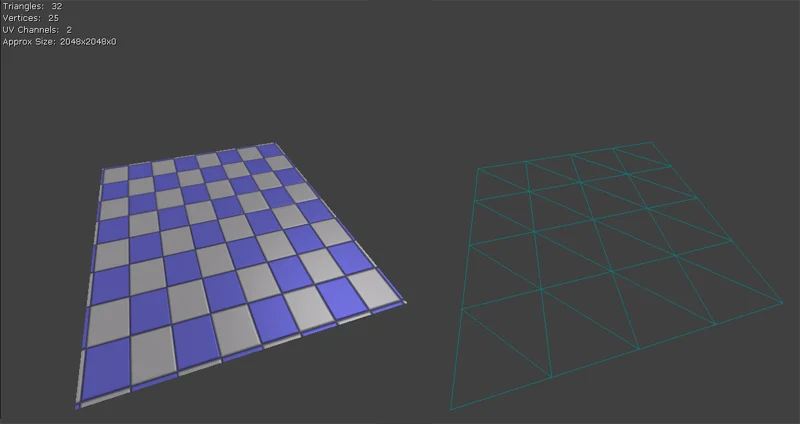
In order to get this 'wave' effect, we'll need to have a polygon plane to work with. Something very simple is all you need. The example above consists of only 16 polygons. Here's a screen shot of that geometry inside the editor.
The next step is to create the material. Here is a brief description about how the material works.
This materials variable (World Position Offset) controls the distortion of the vertex' of the mesh you have selected. Offsetting this means that you will either have to paint out the vertex colours inside of max, or inside of the editor.
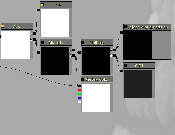
Here is the first shader we will be creating.
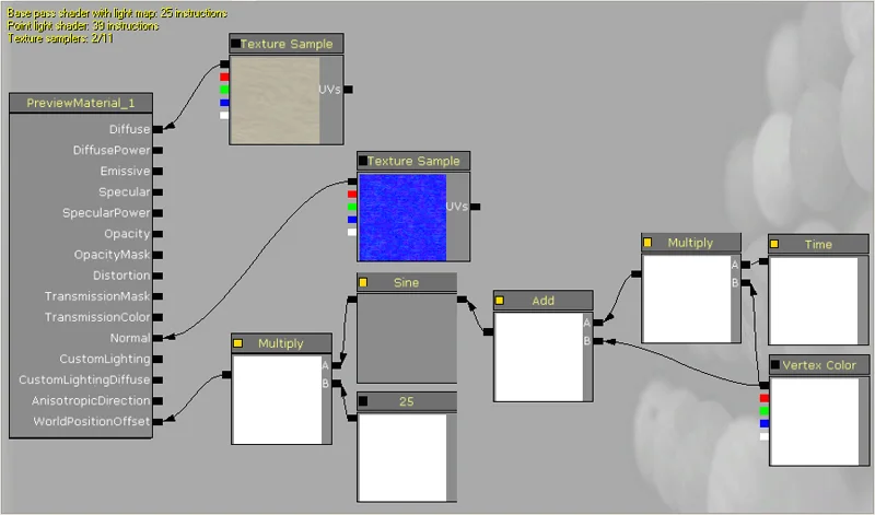
If we start from the right, we have a 'time' variable multiplied to the 'vertex colour' node. This will cause time of each vertex colour to be controlled by the colour value itself. If a vertex is painted black, there will be no 'time' added to it, however the stronger it is painted white, the more powerful it will be.
The reason why we want to cancel out certain vertex colours is because each vertex colour corresponds to the axis' of the world. Red Green Blue = X Y Z. Because of this, if we paint out the red and the green value to black and leave blue white, with this shader the geometry will oscillate in the Z axis.
Because this is 'multiplied' by time, the time will vary based on the duration of time, meaning each vertex will loop, but the entire mesh will not loop perfectly in sync with one another. This of course is dependant on the white values painted on each of the RGB vertex colours.
Next the multiply is 'added' with the vertex colours, this is only to add more 'offset' in the time of the mesh' wave effect.
The sine node causes the vertex' to oscillate (loop) in both the X, Y and Z axis, without this you will not have a 'wave' appearance. In the video example above, this value is set to 2, but the higher you make it, the longer the oscillation period will become (the animation slows down), and like wise, the lower the number, the faster the animation.
This is then multiplied by 25 to make the height values much stronger. Since a vertex colour has a limit to the value it can be painted, this 'multiply' will increase these values, causing a more intense wave.
Also for this to work correctly, we need to make the shader 'transparent'. I will explain this a bit more later on.
That's the basics of the shader. For now, lets keep it 'opaque' and apply it to the polygon plane.
Place your geometry into the scene and move it to a relative height. Make sure that it's not only inches from the ground because it will be 'waving' and if it IS too close to the ground, it will collide, giving it strange results.
Once you apply this to the geometry you will have an animated material, however since new geometry automatically has white vertex colours, it will animate in all 3 axis', X Y and Z.
If you place geometry into the scene, and it's too large to paint, simply scale it down so the vertex' are closer together, making it easier to paint.
For a quick walk through about the 'Mesh Paint Mode' since it is what we'll be using, visit the epic web site located here which will explain how everything works.
http://udn.epicgames.com/Three/MeshPaintReference.html
First off, if you are going to paint something that has a transparent material, you will not be able to view the individual RGB colours, This only works if the material is set to opaque. So if nothing shows up for you with these settings applied, that is why.

Now, with your geometry selected, press the 'Mesh Paint Mode' button located on the top left of the Unreal Editor.
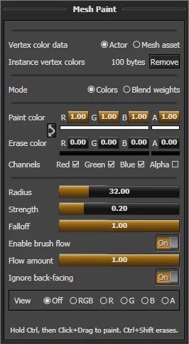
Now, with your geometry selected, press the 'Mesh Paint Mode' button located on the top left of the Unreal Editor.
I will keep my material transparent so i can see the direct effects the vertex painting has on it without any visual artifacts.
First lets paint down everything with a black vertex colour. This will remove any animation that the geometry has.
Once you have this, paint up the 'blue' vertex colour so it's 100% white. If you view the perspective as well as the top camera and hit the 'real time' button (top left of the view window) you will see the animation. With the blue vertex painted white you will see that it animates in the Z axis. Bringing the blue down to a black value and painting in red, you will see that it animates along the X axis, and likewise the green animates along the Y axis.
RGB = XYZ
with this in mind, paint the red and green vertex colours so they're black and give a variation to the blue. Once this is done, you will begin to see a wavy animated effect with the geometry.
If you duplicate this geometry and move it around the level, you will not notice any change in the animation, this is because it's based on 'time' and there is no other variable that changes how it animates.
This next material will change that issue where if you duplicate the mesh, depending on the direction you move it, it will animate at a different offset, making it look like the animations do not match exactly.
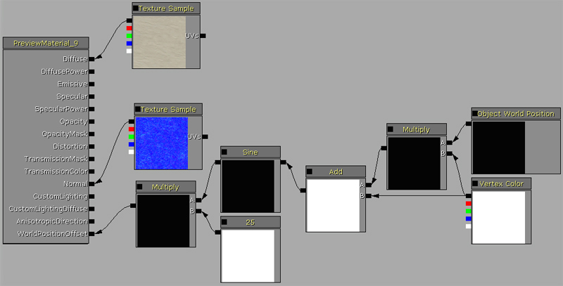
This is what the new shader should look like.
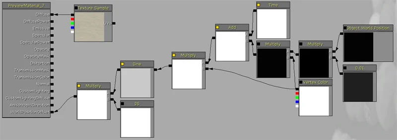
The left side of this shader is basically the same as before, so lets zoom into the right side to get a closer look.
The 'object world position' is an information node that pushes out the location of the geometry this material is applied to and is independent for each piece of geometry, meaning if you have 4 pieces of geometry with this material applied to it, and each one is animated, they would have different 'object world position' information plugging into this shader. Each piece of geometry would animate with an offset to one another.
This is then multiplied by 0.01 because the value is very large at times and we only need a slight change in the value, not a large one.
Since an environment deals with XY and Z coordinates, the object world position contains all 3 of these values, so we will want to multiply the vertex colour by this so just as before, anything painted black will be disabled. The multiply is then added to the 'time', the 'add' is then multiplied by the vertex colour and then goes into the 'sine' node. Again, the 'multiply' that the sine is plugged into only amplifies the save strength.
With this material change, if you move the geometry in the positive of the X Y or Z axis, you will see the wave effect speed up, and like wise, if you move it in the negative axis direction, you will see it slow down.
There is another way to use this 'world position offset' option. This example basically offsets the geometry as the mesh moves. This is perfect for something like bubbles, where you have a blobby piece of geometry that will distort as it moves up.
Here is what the material looks like.
In this example, we removed the 'time' variable from the shader, so the only 'offset' information is given through the assets world location. What this does is the geometry will only animate when the mesh moves.
I should note that a 'moveable' actor will not contain the vertex painting that you paint on that mesh, so painting it then converting it will not work. However, if you paint out the vertex colours in 3d max, maya or a different 3d software and import that, it will keep that information because you export it with the vertex information in tact. It's stored within the mesh itself and is not based on the individual asset in the scene.
This shader is useful for something that's transparent that you want to have look different when you instance it around the scene because it's the actual location that gives the variant information.
Now, the reason why i mentioned making your material 'additive' or 'translucent' is because using the 'world position offset' option creates some strange results. In the image below, there is a solid piece of geometry 'opaque' on the left and an opaque version of these 'world position offset' materials on the right.
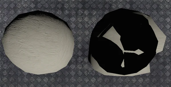
The sphere on the right side of the the image is filled with black areas. These are not shadows, they are the base frame work on the original geometry before the vertex' are animated. Because of this, you get this black clipping plane to deal with and the visuals are nowhere near ideal. This is why in these examples the material needs to be translucent or additive.
This only touches the tip of the ice berg in regards to what the 'World Position Offset' is capable of doing, so i encourage you to experiment and explore with UDK to see what other effects it is capable of doing.
I hope this has helped.
Enjoy.
I hope this tutorial has helped you out. i thank you for your time.